Camera
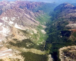
AOP photo of landscape in Crested Butte Colorado
The evolution of high-resolution cameras and image spectrometry is changing the landscape of ecology. Different objects reflect, absorb, and transmit light differently, including light that is visible to the human eye. Cameras measure reflected light energy to capture images of visible light spectrum in three bands that fall within the True Color Red-Green-Blue (RGB) spectrum. When mounted on airplanes, these instruments help scientists measure changes to the Earth's surface over large areas.
Scientists can use digital camera imagery (DCI) to provide critical context of the landscape that lidar or hyperspectral imagery can lack. These data can allow for rapid visual assessment and quantitative delineation of surface (e.g., rock outcrops, roads, water bodies) and vegetation types (e.g., trees, shrubs). DCIs can also be combined with lidar or hyperspectral products. For instance, a DCI image can be draped over a lidar Digital Elevation Model (DEM), providing terrain and True Color landform context simultaneously, which cannot be achieved using individual products.
About the Camera
A medium-format digital camera collects imagery from the visible portion of the electromagnetic spectrum (Red-Green-Blue [RGB]) simultaneously with the lidar and hyperspectral imagery in order to provide high-resolution contextual information with high spatial accuracy. The processed ground spatial resolution of the camera imagery is 0.10 m, compared to the lidar and spectrometer resolution of 1.0 m. The higher spatial resolution allows camera images to provide an order of magnitude finer detail than the spectrometer or lidar. The high-resolution images can aid in identifying features that may not be distinguishable in the spectrometer images, including manmade features (e.g., roads, fence lines, and buildings) that are indicative of land-use change. Information from the images is also used to add color information to each individual point in the discrete lidar point cloud data product (DP1.30003.001).
NEON AOP Camera Sensor History
AOP payloads have used three different PhaseOne cameras since the first flights in 2012. Table 1 lists all cameras that have been used by the NEON AOP and their associated specifications. Table 2 lists the dates when each camera was used, by payload. The camera model used will primarily have implications for final data products through the resolution and instantaneous field of view (IFOV). The IFOV relates to the achievable ground sample distance (spatial resolution), while the sensor dimensions will relate to the total number of pixels in the image.
| Camera Model | Sensor dimensions (pixels) | Lens focal length (mm) | IFOV (µRad) | FOV (deg) | Image size at 1000 m AGL (m) | Ground sampling distance at 1000 m AGL (m) |
|---|---|---|---|---|---|---|
| D8900 | 8984 x 6732 | 70 | 82 | 42 x 32 | 734 x 561 | 0.086 |
| IQ180 | 10328 x 7760 | 70 | 72 | 42 x 32 | 722 x 561 | 0.071 |
| IQ180 | 10328 x 7760 | 80 | 63 | 37 x 28 | 647 x 494 | 0.063 |
| IXU-RS-1000 | 11608 x 8708 | 70 | 63 | 42 x 32 | 728 x 557 | 0.063 |
| iXM-RS150F(future use) | 14204 x 10652 | 70 | 52 | 42 x 32 | 728 x 557 | 0.052 |
| Year | P1 | P2 | P3 |
|---|---|---|---|
| 2013 | D8900 | N/A | N/A |
| 2014 | D8900 | N/A | N/A |
| 2015 | D8900 | N/A | N/A |
| 2016 | D8900 | N/A | N/A |
| 2017 | D8900 | D8900 | IQ180 |
| 2018 | D8900, IXU-RS-1000 | IXU-RS-1000 | IQ180 |
| 2019 | IXU-RS-1000 | IXU-RS-1000 | IQ180 |
| 2020 | IXU-RS-1000 | IXU-RS-1000 | IQ180 |
| 2021 | iXM-RS150F | IXU-RS-1000 | iXM-RS150F |
Sampling Design and Methods
The AOP aircraft normally flies at an altitude of 1000 meters above ground level, although the altitude may vary over mountainous terrain. Adjacent flight line separation is designed to provide 40% cross-track overlap, and the camera acquisition triggering times are set to provide 60% along-track overlap (Figure 1). As the altitude changes due to topographic variations, this will also have an effect on the intended overlap between images. High peaks in the landscape will serve to decrease the overlap, while valleys will increase the overlap. Brightness in images is affected by natural lighting conditions and camera exposure settings, which are typically set to an ISO of 200, aperture 7.1, and shutter speed is set to 1/1000 s. The image capture settings may vary periodically due to natural lighting conditions, however, the shutter speed has a lower limit which prevents blurring in the image due to the forward motion of the aircraft during image exposure.
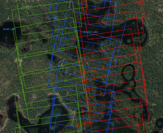
Figure 1 - Sample of the flight track for camera data collected on April 15th, 2019 over the site DSNY showing the extent of overlap among the images. Green, red and blue images were captured in three respective flight lines. (Background from GoogleEarth)
Data Quality and Use
Calibration Flights
After installation of the sensors prior to flight season, the camera requires a geometric and optical calibration. The calibration determines parameters that describe the internal optics of the camera (i.e. focal length) as well as angular offsets between the camera imaging sensor and the inertial measurement unit (IMU), called boresight angles. These parameters are used in the orthorectification algorithm and are required to ensure that the spatial accuracy of the data meets the NEON accuracy requirement of 0.5 m relative to the lidar and between camera images. The required calibration parameters are determined through a flight conducted over Greely, CO that includes the acquisition of flightlines from multiple, differing altitudes and directions. This region is selected because the urban landscape provides a number of different features that can be identified, required for the process of determining the calibration parameters. Data from the boresight calibration flight are not delivered through the portal, but can be provided upon request.
Quality Assurance (QA)
Beginning in 2019, an orthorectification QA check was run for each site to verify the quality of the orthorectification and uncover errors. This check automatically finds "tie points" between overlapping images. Tie points are locations in the two images that correspond to the same object, e.g. a boulder. The calculated distance between the two locations in overlapping images is a measure of the orthorectification error. Figure 5 shows the QA check for the site 2019_YELL_2. Large errors (>6 m) correspond to tie point generation errors and can be ignored. The mean error of 0.171 m shown in this figure indicates the relative spatial accuracy meets the NEON requirement of 0.5 m.
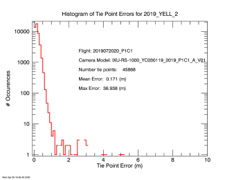
Figure 5 The Tie Point QA Check for 2019_YELL_2.
Metadata
When camera data are downloaded from NEON, a KMZ file is included. The KMZ file can be opened in GoogleEarthPro and contains L1 and L3 image boundaries and filenames, overlaid on a low-resolution image mosaic. The KMZ file facilitates locating individual camera images of interest. The KMZ filename is as follows; YYYY_SITE_V_mosaic.kmz, e.g. 2019_YELL_2_mosaic.kmz. The file will be downloaded to a dedicated Metadata directory within the zipped data package obtained from the portal. Within the KMZ, the low resolution browse image is shown and the tile boundaries are displayed in red, with a red thumbtack in the middle of each tile (Figures 6, 7). Clicking on a thumbtack displays the full filename for that tile.
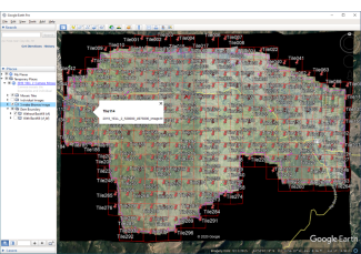
Figure 6 - 2019_YELL_2_mosaic.kmz opened in GoogleEarthPro, showing the low resolution browse image and the L3 tile boundaries.
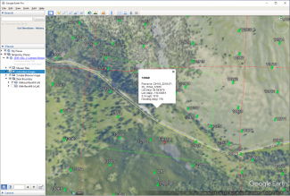
Figure 7 - 2019_YELL_2_mosaic.kmz opened in GoogleEarthPro, showing the low resolution browse image and L1 and L3 image thumbtacks with associated metadata.
Filenames
The filenames of the L1 camera images vary with the year, camera model, and payload. Examples of the image filenames are given in Table 5 of Data Formats & Conventions. The L1 filename gives no indication of the location of the image, but this can be either obtained from the file metadata or from a KMZ file distributed with the files.
Data Products
Raw camera images (L0) are images just as they are recorded. Raw images are processed to correct for exposure and white-balanced to approximate what would be seen by the human eye. Next, they are "orthorectified." Orthorectification projects the image onto a fixed grid on the ground, correcting for distortions caused by the camera optics, the orientation of the camera, and topographic variations of the ground. The result is an image as would be seen looking straight down from a long distance. These images are the L1 data product.
NEON uses a rigorous direct orthorectification algorithm to geo-locate each pixel with less than 0.5 m of absolute error compared to accurately surveyed ground points. Figure 2 shows an example of a raw image (L0) with its associated L1 image after orthorectification. All L1 images are created in the ITRF00 (International Terrestrial Reference Frame 2000) datum and projected into the appropriate UTM (Universal Transverse Mercator) zone.

Figure 2 - Image C0119_2019-07-20_11644_12969 taken from Yellowstone National Park in 2019: left, the raw image, right: the orthorectified image.
The L3 camera product is created by mosaicking all L1 images into a single image and then subsetting the image into 1 km by 1 km tiles. Tiling is performed to keep the mosaic files to a manageable size. The mosaic algorithm preferentially selects the pixels closest to the nadir direction of each image capture. Here, nadir refers to the direction that is perpendicular to the camera's imaging sensor. Preferentially selecting pixels closest to nadir is roughly equivalent to selecting the image pixels nearest to the center of each captured image and reduces the distortions which are greater at the edges of the images. Figure 3 shows the mosaic for the Yellowstone (YELL - D12) site collected in 2019. Figure 4 shows an individual tile corresponding to the red box in Figure 3.
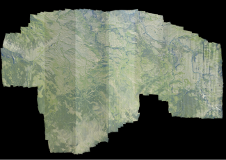
Figure 3 The full mosaic for Yellowstone 2019.
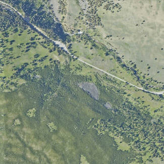
Figure 4 Tile labelled 2019_YELL_2_528000_4976000.tif corresponding to the red rectangle in the previous picture.
The ground sampling distance, or spatial resolution, for the L1 and L3 camera products is 0.25 m for 2016 and earlier, and was improved to 0.10 m for 2017 and after. Both the L1 and L3 data is distributed in the form of 8-bit jpeg-encoded GeoTIFF (gtif) files. The gtif files contain embedded metadata defining the location and extent of the images. These files can be viewed in their proper geographic location in geospatial software packages such as QGIS, ArcGIS, and ENVI, among others. Areas with no data are stored as zeros and will appear black in the L1 and L3 images. An individual L1 camera image ranges from 30-50 MB in size while a single L3 tile is 50-100 MB in size. An entire NEON site could contain several thousand L1 images and several hundred L3 mosaic tiles.
The L0 images do not constitute a data product and are not normally distributed but can be delivered upon request. Note that the PhaseOne cameras save L0 images in a proprietary format named IIQ. Although this format meets the formal specifications of a TIFF, the actual image data is stored in a proprietary TIFF tag and is unreadable by most image viewers. The full resolution image data can be extracted from the raw files using the software IXCapture or CaptureOneDB from Phase One Industrial. Similar to L1 and L3 images, the L0 images are stored with 8-bits, and regions without information are encoded with zeros, leading to black regions on the image.
Camera Data Products
- High-resolution orthorectified camera imagery (DP1.30010.001)
- High-resolution orthorectified camera imagery mosaic (DP3.30010.001)